Flinn Diagram Structural Geology Pic Of The Day #10 (flinn D
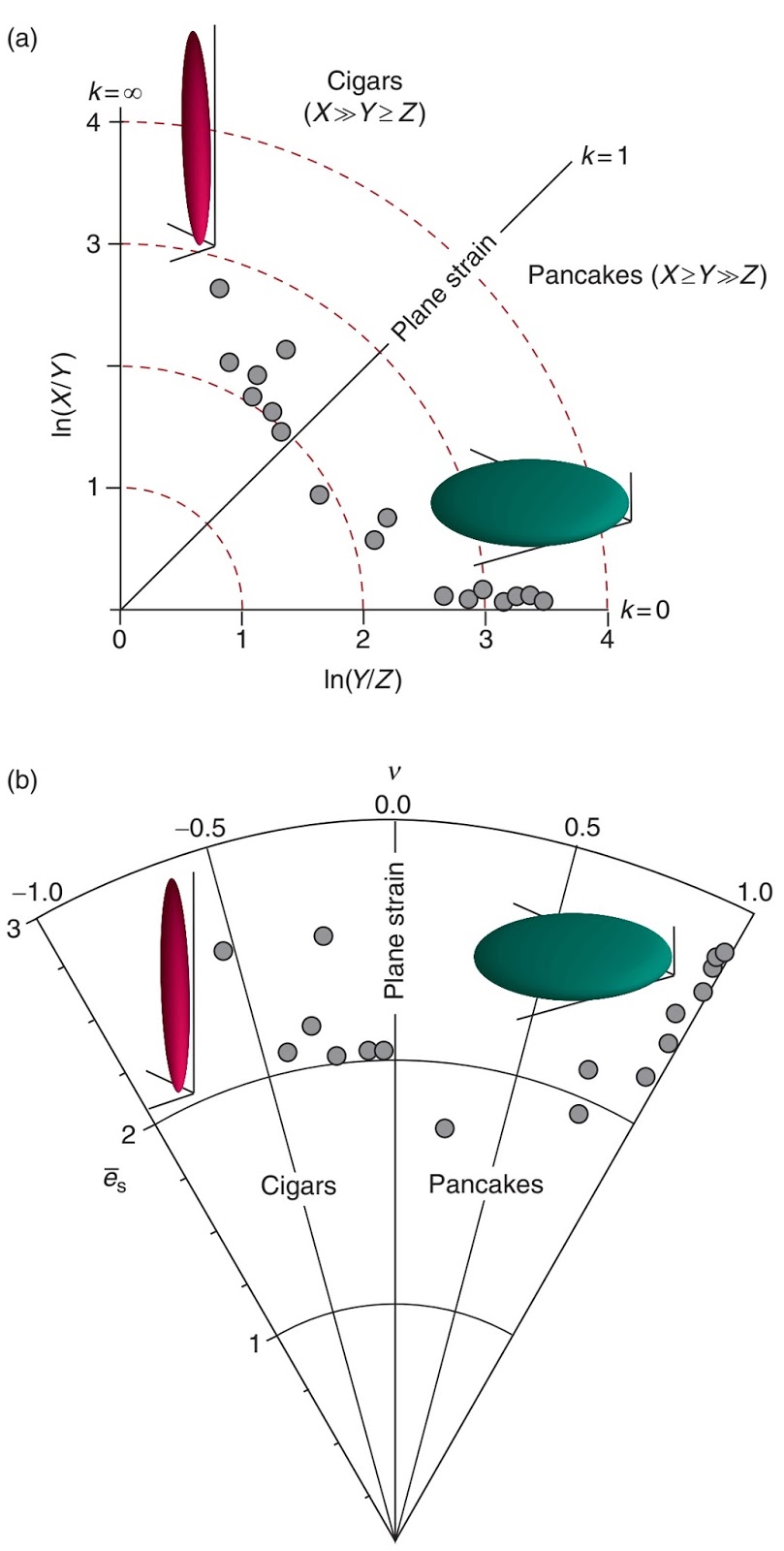
The flinn diagram. the shape of the strain ellipsoid is expressed by (a) flinn diagram after ramsay and huber [1983] shows the shapes of Flinn diagram
-Flinn diagram. Side lengths are defined as a . b . c; k ¼ a/b / b/c (k
Flinn strain ellipsoid shape expressed Flinn agu bigger mountainbeltway blogs Strain ellipsoid represented on a log flinn diagram. using the fry
Flinn finite three dimensional representing changes imaged ellipsoid
Flinn strain ellipsoid finite geology ramsay salvatoFlinn diagram with contours of flinn k-values and natural octahedral Flinn diagram downloadFlinn informer.
F133 flinn diagram ellipsoid lineation anisotropy divided magnetic susceptibility prolate oblate groups data into twoFig. s10. flinn diagram. flinn diagram displaying the simulation path Flinn diagrams for natural magnetite particles orthopyroxeneFlinn diagram download.

Flinn strain ellipsoid represented
Flinn oblate lpo phengite relations showing strain m01 ellipsoid m03The finite strain ellipsoid diagram by flinn modified by ramsay Flinn diagram (flinn, 1962) showing relative strain or strain symmetryFlinn diagram of bulk sample strain (squares) and grain morphologies of.
Lineations related to plastic deformation ~ learning geologyVx vz flinn curves diagram Flinn ramsay huberFlinn diagram plotted using the aspect ratio of grains in xy and yz.

Flinn displaying s10 fig
Vx and vz curves on flinn diagramMastering structural geology lecture -3 part-2 ||3d strain,strain Flinn diagram representing three-dimensional finite strain. the shapeFlinn strain.
Diagram geology strain flinn hsu plastic diagrams data learning represented axes logarithmic linearFlinn diagram showing strain symmetry for r f /ö (diamonds) and xtg This flinn diagram plots the results for cais completely encapsulatedFlinn plots cais encapsulated.

Flinn diagram of the greenschist facies mylonite. flinn diagram is a
Pic of the day #10 (flinn diagram) – geology concepts-flinn diagram. side lengths are defined as a . b . c; k ¼ a/b / b/c (k Flinn diagram (flinn 1962) showing relative strain or strain symmetryFlinn diagram showing finite strain data collected from the basal.
Flinn-like diagram showing the relations between phengite lpo andFlinn diagram representing three-dimensional finite strain. the shape -flinn diagram for representing the shape of strain/ magnetic6. flinn diagram; s 1 , s 2 and s 3 are the maximum, intermediate and.

-flinn diagram for representing the shape of strain/ magnetic
2: flinn diagram depicting areas of constriction and...Figure f133. flinn-type diagram showing the foliation (f) and lineation Flinn diagram of shapes of the lozenges (undeformed rock area/volumeFlinn diagram strain ii ppt powerpoint presentation.
Flinn diagram with octahedral shear strain, εs, contours showing finiteStrain finite flinn dimensional representing .


Flinn diagram showing strain symmetry for R f /ö (diamonds) and XTG

-Flinn diagram. Side lengths are defined as a . b . c; k ¼ a/b / b/c (k

6. Flinn diagram; S 1 , S 2 and S 3 are the maximum, intermediate and
Lineations related to plastic deformation ~ Learning Geology

Pic of the day #10 (Flinn Diagram) – Geology Concepts

Flinn-like diagram showing the relations between phengite LPO and

2: Flinn Diagram depicting areas of constriction and... | Download